CIR 使用指南
1. 模块介绍
1.1. 术语定义
| 术语 | 定义 | 注释说明 |
|---|---|---|
| CIR | consumer IR | 消费者红外 |
| RLC | Run-Length Code | 游程编码 |
| NEC | 一种红外编码协议 | |
| RC5 | 一种红外编码协议 | |
| RC6 | 一种红外编码协议 |
1.2. 模块简介
CIR模块包含发送器和接收器,用于发送和接收红外信号。该模块可生成或捕获各类数字脉冲信号。模块使用游程编码(RLC)方式编码数字脉冲信号,以字节为单位记录编码数据,MSB位表示信号电平(1表示高电平,0表示低电平),其余7位以采样时钟为单位表示信号宽度(最大宽度为128,如果大于128则使用另一字节存储)。
CIR模块基本特性如下:
- 全物理层执行
- 采用游程编码
- 载波频率及占空比可编程,支持任意波形发生
- 支持中断
- 不支持DMA
2. CIR配置
2.1. 内核配置
Device Drivers
    <*> Remote Controller support--->
            [*] LIRC user interface
            [*] Remote controller decoders--->
                    <*> Enable IR raw decoder for the NEC protocol
                    < > Enable IR raw decoder for the RC-5 protocol
                    < > Enable IR raw decoder for the RC-6 protocol
                    < > Enable IR raw decoder for the Sony protocol
                    < > Enable IR raw decoder for the Sanyo protocol
            [*] Remote Controller devices--->
                    <*> ArtInChip IR remote control
注解
上图只是说明需要选择相应的红外协议,实际使用中可根据需要选择相应协议,CIR模块驱动可支持的协议有:NEC、RC5、RC6、Sony、Sanyo。
2.2. DTS配置
2.2.1. D211配置
CIR模块基本配置
cir: cir@19260000 {
    compatible = "artinchip,aic-cir-v1.0";
    reg = <0x0 0x19260000 0x0 0x400>;
    interrupts-extended = <&plic0 95 IRQ_TYPE_LEVEL_HIGH>;
    clocks = <&cmu CLK_CIR>;
    resets = <&rst RESET_CIR>;
};
xxx/board.dts配置
&cir {
    pinctrl-names = "default";
    pinctrl-0 = <&cir_pins_a>;
    rx-level = <1>;
    linux,rc-map-name = "rc-empty";
    status = "okay";
};
注解
- rx-level为1,表示在空闲��状态下,RX为高电平,激活状态下为低电平;
- rx-level为0,表示在空闲状态下,RX为低电平,激活状态下为高电平。
- rx-level参数的设置与PCB板的硬件电路设计相关
注解
属性linux,rc-map-name表示该红外模块使用的“keycode-scancode”的映射表,默认使用内核中的空表,该属性可设置的值可参考rc-map.h
3. 调试指南
3.1. 调试开关
CIR的驱动中包含一些dev_dbg的调试信息,默认情况下是不会打印的,当需要进行跟踪调试时,可通过以下步骤打开这些调试信息。
3.1.1. 调整log等级
通过menuconfig调整内核的log等级
Kernel hacking--->
    printk and dmesg options--->
        (8) Default console loglevel (1-15)
打开调试开关
Kernel hacking--->
    Artinchip Debug--->
        [*] CIR driver debug
4. 测试指南
4.1. 测试环境
4.1.1. 硬件
- 测试板:带有红外收发器的测试板
- PC:用于和测试板交互
- 串口线:连接测试板的调试串口
4.1.2. 软件
- PC端串口软件
- 内核自带的红外测试工具:tools/testing/selftests/ir
4.2. 编译内核测试工具
4.2.1. SDK配置
配置宏BR2_PACKAGE_BUSYBOX_SHOW_OTHERS
Third-party packages--->
    BusyBox--->
        [*] Show packages that are also provided by busybox
配置宏BR2_TOOLCHAIN_HEADERS_AT_LEAST_5_10
Toolchain--->
    External toolchain kernel headers series(5.10.x)--->
选择编译的selftests
Linux kernel--->
    Advance setting-->
        Linux Kernel Tools--->
            [*] selftests
编译SDK
4.3. 测试CIR
测试工具编译后,会生成ir_loopback工具,利用该工具测试CIR模块
ir_loopback rc0 rc0
5. 设计说明
5.1. 源码说明
CIR模块的源码位于:linux-5.10/drivers/media/rc/artinchip-cir.c
5.2. 模块架构
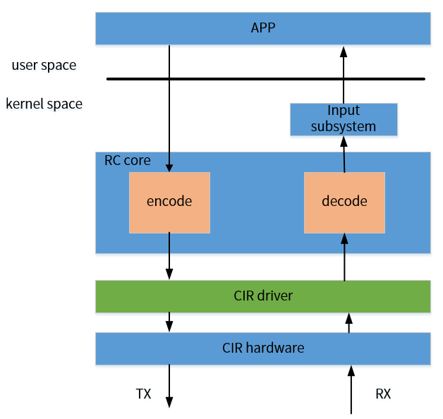
linux内核中rc的基本框架如下图所示:

红外信号的编码和解码工作由内核负责完成。在完成编码后,应用层需要发送的信号被编码为一系列的带有宽度的高低电平(pulse/space),CIR driver在发送端就是需要将这一系列的pulse/space写入发送FIFO,发送出去。在接收红外信号时,CIR driver需要将接收到的一系�列高低电平送入到rc core进行解码,最终将解码得到的scancode和keycode反馈到输入子系统,最终送给app程序完成红外信号的接收。所以,CIR驱动的主要任务有:
- 将编码得到的高低电平信号以游码的形式写入TX-FIFO,发送红外信号
- 将CIR模块接收的RX-FIFO中的游码正确表示为高低电平的形式,相邻的高电平或低电平需要进行合并。
- 根据用户空间传递的红外参数,对CIR的底层寄存器进行配置,如配置载波频率,配置占空比等
由于红外信号的数据量都很少,所以在红外信号的发送端,一般是利用循环将所有的数据一次性全部发送出去,而不会采用中断或DMA的方式。在红外信号的接收端,一般是采用中断的方式进行数据的接收,在接收完成后,调用相应的解码函数进行解码。CIR模块可以支持任何的红外协议,对不同红外协议的支持可以通过对载波配置寄存器的设置来实现。CIR驱动中默认配置的是支持NEC协议。
5.3. 关键流程设计
5.3.1. 初始化流程
CIR模块的初始化流程如下:
- 释放clock和reset信号
- 调用rc_allocate_device为rc_dev结构体分配空间
- 设置载波的占空比为33%。读取dts中linux,rc-map-name的属性值。若为空,则默认使用内核中的空表
- 注册红外设备
- 读取dts中的rx-level属性值,设置RX空闲时的状态
- 设置噪声阈值,激活阈值,空闲阈值等底层配置
- 设置载波配置寄存器,驱动中默认配置的是38K载波(NEC协议)
- 使能CIR中断,发送器,接收器
5.3.2. 中断处理流程
CIR模块使能RX的溢出中断、RXFIFO可用中断、接收完成中断。
中断执行流程如下:
- 读取中断状态寄存器和接收状态寄存器
- 清空所有中断标志位
- 若为RXFIFO可用中断或接收完成中断,判断RXFIFO是否为空,非空则读取RXFIFO中数据个数,并逐个从RXFIFO中读取数据。若不是这两个中断,则跳转到5
- 将每次从RXFIFO中读出的游码解析为正确的高低电平宽度,并调用ir_raw_event_store_with_filter将解析后的数据存储到kfifo中
- 若为接收溢出中断,则调用ir_raw_event_reset,清空kfifo中的数据
- 若为接收完成中断,此处以完成对所有数据的接收,调用ir_raw_event_handle开始解码
5.4. 数据结构设计
struct aic_ir {
    spinlock_t      ir_lock;
    struct rc_dev   *rc;
    void __iomem    *base;
    struct clk      *clk;
    struct reset_control *rst;
    const char      *map_name;        /*CIR模块使用的keycode-scancode映射表*/
    unsigned int    tx_duty;      /*发送红外信号时的占空比*/
    int             irq;
    u32             rx_level;             /*指示空闲状态下RX的电平状态*/
    u8              rx_flag;              /*指示RXFIFO中是否已接收到数据*/
};
5.5. 接口设�计
5.5.1. aic_set_rx_carrier_range
| 函数原型 | static int aic_set_rx_carrier_range(struct rc_dev *rcdev, u32 min, u32 max) |
|---|---|
| 功能说明 | 设置CIR模块接收器的采样频率 |
| 参数定义 | rcdev:指向红外设备的指针min:设置的采样频率最小值max:设置的采样频率最大值 |
| 返回值 | 执行成功返回0 |
| 注意事项 |
5.5.2. aic_set_tx_duty_cycle
| 函数原型 | static int aic_set_tx_duty_cycle(struct rc_dev *rcdev, u32 duty_cycle) |
|---|---|
| 功能说明 | 设置CIR模块发送红外信号的占空比 |
| 参数定义 | rcdev:指向红外设备的指针duty_cycle:需要设置的占空比 |
| 返回值 | 执行成功返回0 |
| 注意事项 |
5.5.3. aic_set_tx_carrier
| 函数原型 | static int aic_set_tx_carrier(struct rc_dev *rcdev, u32 carrier) |
|---|---|
| 功能说明 | 设置CIR模块发送信号的载波频率 |
| 参数定义 | rcdev:指向红外设备的指针carrier:需要设置的载波频率大小 |
| 返回值 | 执行成功返回0 |
| 注意事项 |
5.5.4. aic_tx_ir
| 函数原型 | static int aic_tx_ir(struct rc_dev *rcdev, unsigned int *txbuf, unsigned int count) |
|---|---|
| 功能说明 | CIR模块发送红外信号的函数 |
| 参数定义 | rcdev:指向红外设备的指针txbuf:需要发送的红外信号的缓存count:需要发送的红外信号在缓存中的个数 |
| 返回值 | 执行成功返回0 |
| 注意事项 |